
PCB Bow and Twist Measurement method covers three procedure used to determine the bow and twist percentage of individual rigid printed boards, rigid portions of rigid-flex printed boards, and/ or multiple printed panels.
Measurements on non-rectangular samples pose a unique testing problem and may necessitate a careful evaluation of the requirements imposed by the users of this test method. This test method does not describe the special considerations necessary when testing the bow and twist of printed board assemblies (i.e., component placement & weight, edge supports & connectors, etc.).
Bow (Sheet, Panel, or Printed Board) is The deviation from the flatness of a board characterized by a roughly cylindrical or spherical curvature such that, if the product is rectangular, its four corners are in the same plane (see Figure 1).
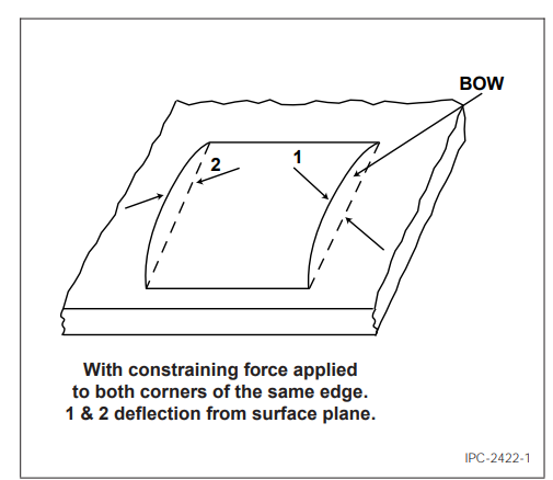
Figure 1 Bow
Twist is the deformation of a rectangular sheet, panel, or printed board that occurs parallel to a diagonal across its surface, such that one of the corners of the sheet is not in the plane that contains the other three corners (see Figure 2).
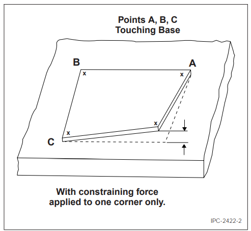
Figure 2 Twist
Applicable Documents
IPC-T-50: Terms and Definitions for Interconnecting and Packaging Electronic CircuitsIPC-TM-650 Test Methods
Test Specimens: The test specimens shall be in the form of either printed boards or multiple printed panels (single-sided, double-sided, multilayer, or rigid-flex boards).
For non-rectangular test specimens, the most convenient way to measure bow and twist is by approximating a rectangle over the test specimen. To accomplish this, an imaginary rectangle that totally encloses the sample must be superimposed over the test specimen. The dimensions of this superimposed rectangle should be the smallest that will fully enclose the specimen. Although this technique will give an approximation of bow and twist, the actual noted values will be less than the actual bow and twist of the sample.
Equipment/ Apparatus
Precision surface plate
Thickness measurement shims (feeler or pin gauges)
Leveling jacks
Standard metrology height dial indicator gauge
Gauge blocks
Linear measuring devices of suitable accuracy
Micrometer of suitable accuracy for thickness measurement
Procedure: Unless otherwise specified, testing shall be performed at standard laboratory conditions (see IPC-TM- 650, Section 1.3).
Bow Measurement
Place the sample on the surface plate. While applying sufficient pressure to flatten the test sample, measure the length and width of the sample and record it as length (L) & width (W) (see Figure 3).
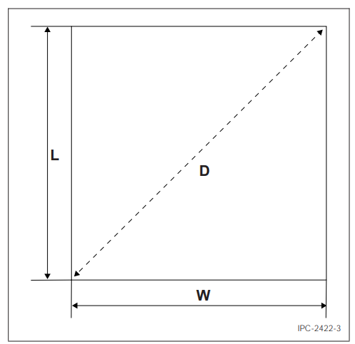
Figure 3 External Measurements
Calculate the size of the feeler/pin gauge (Go/No-Go) to be used for maximum bow percentage using the following formula:
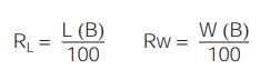
Where:
RL = Go/No-Go feeler/pin gauge size for sample length
RW = Go/No-Go feeler/pin gauge size for sample width
L = Length measurement as determined above
W = Width measurement as determined above
B = Maximum allowable bow percentage
Place the sample to be measured on the surface plate with the convex of the sample facing upwards. For each edge, apply sufficient pressure on both corners of the same sample edge to ensure contact with the surface (see Figure 4).
Attempt to slide the feeler/pin gauge of thickness RL under the length side(s) of the sample and RW under the width side(s) of the sample. If the Go/No-Go feeler/pin gauge slides between the sample and the surface plate, the bow in that direction exceeds the allowable percentage used in the calculation above. Repeat this procedure until all sides of the sample have been measured.
Calculate the percentage for the bow as follows:
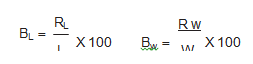
Where:
BL = Percentage bow in the length direction
BW = Percentage bow in the width direction
RL = Measured maximum feeler/pin gauge size across sample length
RW = Measured maximum feeler/pin gauge size across sample width
L = Length measurement as determined above
W = Width measurement as determined above
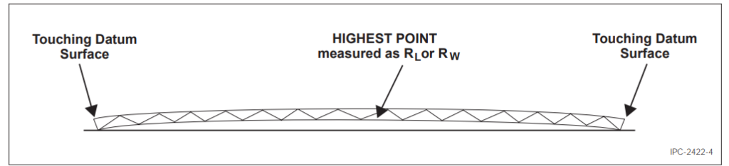
Figure 4 Bow Measurement
Twist Measurement
Place the sample on the surface plate. While applying sufficient pressure to flatten the test sample, take the diagonal measurement across the sample and record it as D (see Figure 3).
Calculate the size of the feeler/pin gauge (Go/No-Go) to be used for maximum twist percentage using the following formula:
R=2(D)(T)/10
Where:
R = Go/No-Go feeler/pin gauge size
D = Diagonal measurement across the sample as determined above
T = Maximum allowable twist percentage
Place the sample to be measured on the surface plate with any three corners of the sample touching the surface. Apply sufficient pressure (if necessary) to only one corner of the sample to ensure three of the four corners are in contact with the surface plate. It may be necessary to turn the sample over to accomplish this (see Figure 5).
If it is not possible to get three corners of the sample to touch the surface plate by restraining only one corner, this production test is not applicable and the referee test described in 5.3 shall be used.
Attempt to slide the feeler/pin gauge of thickness R under the corner not touching the surface plate. If the Go/No-Go feeler/pin gauge slides under the corner not touching the surface plate without lifting any of the other three corners of the sample from the surface plate, the twist in that direction exceeds the allowable percentage used in the calculation above. Repeat this procedure until all corners of the sample that can be measured using this technique have been measured.
Calculate the percentage of twist as follows:
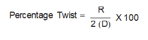
Where:
R = Go/No-Go feeler/pin gauge size
D = Diagonal measurement across the sample as determined above
Note: This formula includes a factor of two because, by constraining one corner of the sample, the vertical deflection of the twist is approximately doubled.
Referee Method (Twist)
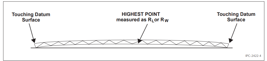
Place the sample to be measured on the datum surface with the two lower opposite corners touching the datum surface or on a raised parallel surface of equal height from the datum surface (see Figure 6).
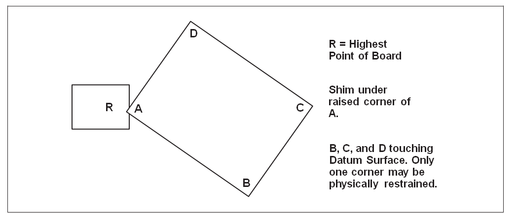
Figure 5 Measurement of Twist
Support the other two corners with leveling jacks or some other appropriate devices, ensuring the two raised corners are of equal height from the datum surface. This may be checked by using the dial indicator (see Figure 7).
Using the dial indicator, measure the highest raised portion on the board and record the reading as R1 (see Figure 8).
Without disturbing the sample, take a reading with the dial indicator on one of the corners contacting the surface (R2) and record the reading (see Figure 8).
Take the diagonal measurement of the sample and record the reading.
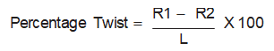
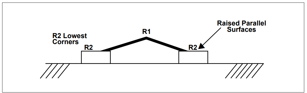
Figure 6 Sample Placement
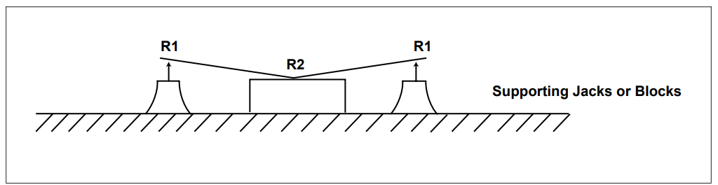
Figure 7 Corners Supports
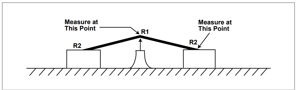
Figure 8 Highest Point Measurement
EMSxchange Enables you to select a Printed Circuit Board, PCB Assembly, cable & wire harness assembly, and box-build suppliers meeting your Required Electronic Manufacturing Capability, capacity, and Certification Criteria from a global Electronic contact manufacturer base.
EMSxchange takes complete responsibility and ownership for your electronic manufacturing process and all its deliverables from contract manufacturing supplier selection to manufacturing to quality inspection to shipment and delivery to your door.
EMSxchange Electronics Product Design and Electronic Manufacturing Services Partner Profile:
Argus Systems (AESPL) Electronics Manufacturing – PCB, PCBA, Cable Assembly, Box Build, Testing.
Argus Systems (AESPL) Product Engineering – Electronics system design Services & consulting
Contact sales@sysargus.com to discuss How Argus Systems can support for your Electronics Design Design and Electronics Manufacturing Services ( EMS) Requirements.