
Thermal Management Considerations for PCBs- Measurement techniques and heat conduction
Thermal Resistance
- TSP Method (temperature sensitive parameter)
- Meets military specifications
- Use forward voltage drop of the calibrated diode to measure a change in Tj due to known power dissipation
Thermal resistance calculation
- Recall the formula for junction temperature:
TJ = (PD x qJA) + TA - Rearranging equation, thermal resistance calculated by:
qJA=DTJ/PD=TJ-TA/PD
where TJ is junction temp, TA is ambient temp and PD is power dissipation
TSP Calibration
- TSP diode calibrated in constant temperature oil bath, measured to ±0.1°C
- Calibration current low to minimise self-heating
- Normally performed at 25°C and 75°C
Temperature coefficient
- Temperature coefficient is known as the K-factor
- Calculated using K=T2-T1/VF2-VF1 at constant IF
where:
K=Temperature coefficient (°C/mV)
T1,2 = lower and higher test temperatures (°C)
VF1, F2=Forward voltage at IF and T1,2
IF=Constant forward voltage measurement current
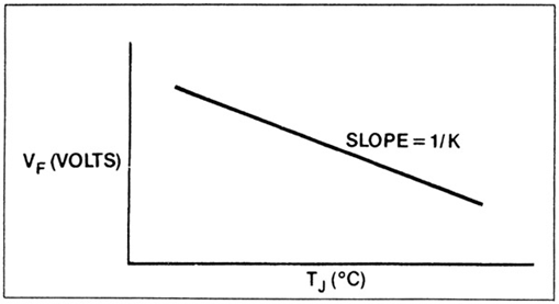
Calibration graph
- K-factor measured from the inverse of slope
Thermal resistance measurement
- Constant voltage and constant current pulses were applied to test the device
- Constant current pulse is the same value as used to calibrate the TSP diode
- This is used to measure forward voltage
- Constant voltage pulse used to heat test device
- Constant voltage (heating) pulse much longer than constant current (measurement) pulse to minimize cooling during the measurement
- Typically >99:1ratio
- Measurement cycle starts at the ambient temperature
- Continues until the steady state reached, i.e. thermal equilibrium
- Thermal resistance is calculated by:
qJA=DTJ/PD=K(VFA-VFS)/VH ´ IH where:
VFA=forward voltage of TSP at ambient temp (mV)
VFS=Forward voltage of TSP at equilibrium (mV)
VH=Heating voltage (V)
IH=Heating current (A)
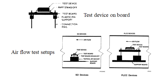
Test ambient
- Measurement of qJA
- Devices soldered to special thermal resistance test boards
- 8-9 mil (200-225µm) standoff from board
- Placed in a box of known volume (1cu ft if you’re American!)
- Temperature rise measured
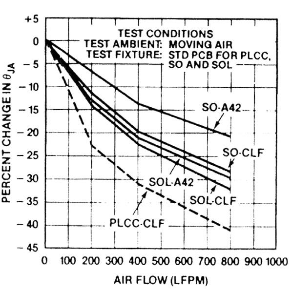
Air flow tests
- Ambient test can also use moving air
- Air flow passed over device at known constant rate
- Required for calculations involving active cooling
- Similar setup to static ambient test
Test setups
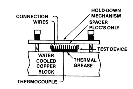
qJC Tests
- Test device held against an infinite heatsink
- This comprises a massive, water-cooled copper block, kept at 20°C
- In this way, qCA (case-ambient) is very close to zero, so any measurement is purely qJC (junction-case)
- SO devices mounted with bottom of package against heatsink, using thermal grease for good conductivity
- PLCC devices mounted upside down, with top of package against heatsink
- Spacer used on bottom side to prevent heat loss from here
PLCC qJC test setup
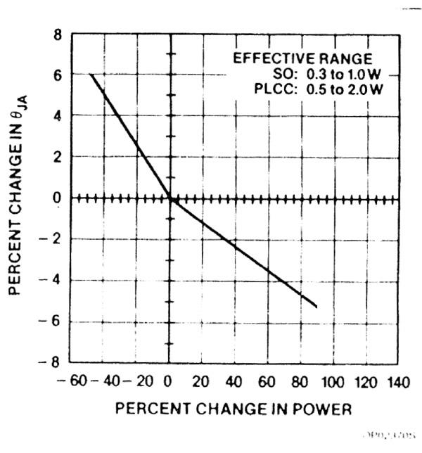
qJC data
- Power dissipation has an effect on thermal resistance
- Must be considered when calculating cooling requirements
Other factors affecting qJC
- Lead-frame design, pad size
- Larger pads reduce thermal resistance for given die size
- Lead-frame material – Alloy 42 or copper
qJA data
- Air flow also affects qJA
- Important consideration for forced-air cooling
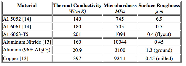
Heatsinks
- Purpose of a heatsink is to conduct heat away from a device
- Made of high thermal conductivity material (usually Al, Cu)
- Increased surface area (fins etc) helps to remove heat to ambient
- Interface between heatsink and device important for good thermal transfer
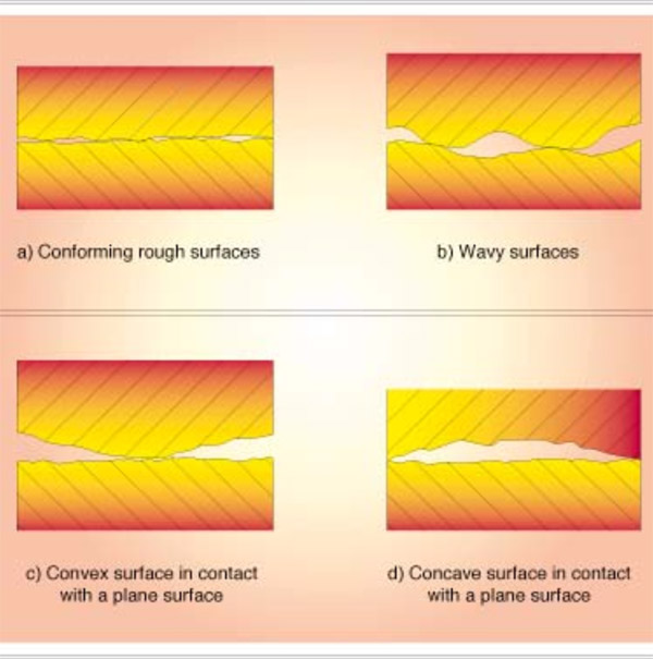
Interface roughness
- Surface roughness at interface between two materials makes a huge difference to thermal conductivity
- Various different contact configurations on microscopic scale
Surface roughness
Surface roughness
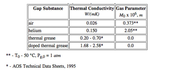
- Air gaps act as effective insulators
- Need some interstitial filler
- Many types available, including greases, elastomers, adhesive tapes
- Seen by consumers e.g. in PC processor heatsink/fan kits
Interstitial filler materials
Solid interfaces
- Conforming rough surfaces can have high conductivity:
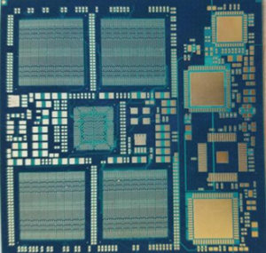
Heat Conduction in a PCB
- PCB is layered composite of copper foil and glass-reinforced polymer (FR4)
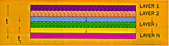
Heat conduction in PCB
- Can treat this layered structure as homogeneous material with two different thermal conductivities
- Heat flow within plane is kIn-plane
- Heat flow through thickness of plane is kThrough
Conductivity Equations
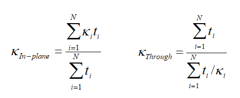
where t is thickness of given layer and k is thermal conductivity of that layer
Sample results
- Total PCB thickness is 1.59mm
- PCB comprises only copper and FR4 layers
- k of copper is 390 W/mK
- k of FR4 is 0.25 W/mK
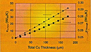
Conclusions from results
- Even for thin copper layers, kIn-plane is much greater than kThrough
- As FR4 has very low thermal conductivity, a continuous copper layer will dominate heat flow
- Because of this, thermal conduction is not efficient where no continuous copper path exists
Refining calculations
- Trace (signal-carrying) copper layers have much less effect on heat transfer than planes
- Trace layers can normally be excluded from calculations
- If required, conductivity of trace layer can be calculated from where fi is fractional copper coverage
Summary
- TSP Method for measuring junction temperatures
- Thermal resistance test methods – junction-air and junction-case
- Effects of power dissipation and airflow on thermal resistance
- Interface resistance
- Use of interstitial materials to decrease this
- Heat conduction in copper-clad PCB dominated by in-plane transfer
- Trace layers have only a small contribution to total conduction
- FR4 is a good insulator!
EMSxchange Enables you to select a Printed Circuit Board, PCB Assembly, cable & wire harness assembly, and box-build suppliers meeting your Required Electronic Manufacturing Capability, capacity, and Certification Criteria from a global Electronic contact manufacturer base.
EMSxchange takes complete responsibility and ownership for your electronic manufacturing process and all its deliverables from contract manufacturing supplier selection to manufacturing to quality inspection to shipment and delivery to your door.
EMSxchange Electronic Manufacturing Partners Profile includes:
Argus Systems (AESPL) – PCB, PCBA, Cable Assembly, Box Build, Testing.