
QUALITY CONFORMANCE TEST COUPONS FOR PRINTED WIRING BOARDS
This Article establishes quality conformance test coupons, their selection and adoption criteria in rigid single-sided (type-1), double-sided (type-2), and multilayered (type-3) lead- lead-through-board mountable printed wiring board manufacture.
REFERENCE STANDARDS
IPC 2221 – Generic Standard on Printed Board Design.
IPC-T-50 – Terms and Definitions for Interconnecting and Packaging Electronic Circuits.
Quality conformance (QC) test coupons should be a part of every panel that is used to produce printed wiring boards. The selection and adoption of test coupons should be in accordance with the standard.
All applicable configurations of test coupons (QC test coupons) Should be defined on the master drawing. Test coupons should reflect the specific board characteristics like meeting the requirements for holes, conductors, spaces, etc.
Composite printed boards Should have separate coupons for the top sideboard, the bottom sideboard, and the composite board. Individual test coupons are designed to evaluate specific individual characteristics of the printed boards they represent.
Test Coupons
The A coupon Should contain holes with the largest diameter components hole on the printed board and land associated with that hole diameter that can be fitted on a 2.54 mm grid to a maximum hole size of 1.905 mm.
The B coupon Should contain holes with the smallest diameter via hole on the printed board and land associated with that hole diameter down to a minimum of 0.15 mm.
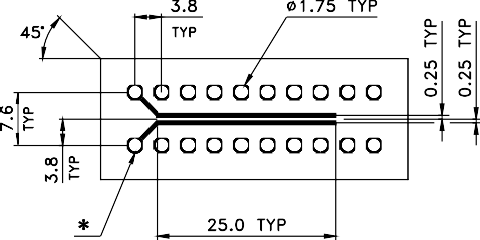
Test coupons A and B & E shown in Figure 2 Should be included on all the conductive layers (external as well as internal layers) test coupons C & J or G shown in Figure 3 Should be confined to external layers.
Test Coupon Quantity and Location
The location of construction integrity coupons should be positioned within 12.7 mm of the printed board profile to reflect build and plating characteristics.
The minimum number of test coupons per panel, and the requirements for positioning the test coupons Should be in accordance with Table 1 and Figure 1, show an example of coupon location concepts.
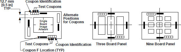
FIGURE 1: LOCATION OF TEST CIRCUITRY
- TABLE-1 :TEST COUPON LOCATION & FREQUENCY
| Test Coupon | Inspection | No. of Test Coupon per Panel | Location on the Panel | ||
| Type 1 | Type 2 | Type 3 | |||
| A and B | Hole Solderability PTH Integrity Bond Strength (USH) Rework Simulation (PTH) Plating Thickness Thermal Stress | 4 | 4 | Opposite Corners | |
| C | Peel Strength | 2 | 2 | 2 | Optional |
| E | Moisture & Insulation Resistance | 1 | 1 | 1 | Optional |
| J or G | Solder Mask/ Resist | 1 | 1 | 1 | Optional |
Test Coupon Identification
QC test coupons Should carry the following reference numbers for identification and traceability.
- Part number and revision status
- Manufacturing lot number
- Date code
- Manufacturer’s identification/logo
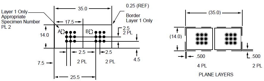
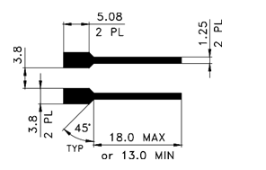
TEST COUPON A and B
TEST COUPON-E
FIGURE-2: QC TEST COUPONS A and B & E
TEST COUPON – C
(External Layers only)
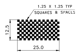
TEST COUPON – J or G
FIGURE-3: QC TEST COUPONS C & J or G
EMSxchange Enables you to select a Printed Circuit Board, PCB Assembly, cable & wire harness assembly, and box-build suppliers meeting your Required Electronic Manufacturing Capability, capacity, and Certification Criteria from a global Electronic contact manufacturer base.
EMSxchange takes complete responsibility and ownership for your electronic manufacturing process and all its deliverables from contract manufacturing supplier selection to manufacturing to quality inspection to shipment and delivery to your door.
EMSxchange Electronic Manufacturing Partners Profile includes:
Argus Systems (AESPL) – PCB, PCBA, Cable Assembly, Box Build, Testing.