

CAF failures
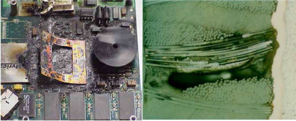
What exactly is CAF?
Conductive Anodic Filament
CAF is the Formation of Solid Cu Filament between different nets within PCB at different potentials.
Follows a glass weave pathway internally in the PCB.
Acts as dead short and then possibly the fire.
Multiple-step Process (PCB Internally)
- Pathway Formation between different PCB Nets internally
- Separation of glass/resin interface
- Incomplete wetting of initial coating of resin to glass
- PCB / PCBA Fabrication (Therm / Mech / Chem)
- Degradation of glass/resin bond – Temp/Humidity
- Can be Hollow Fiber
- Separation of glass/resin interface
- Electromigration-Ionic (EM) down a Pathway – Anode to Cathode
- Growth of Solid Cu Filament – Cathode to Anode
CAF Failure -can occur before solid Cu filament formation.
Electro-migration (EM) can lead to catastrophic drops in resistance.
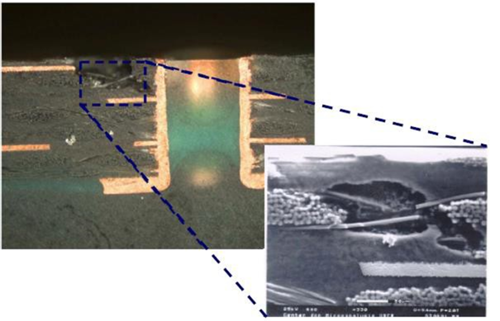
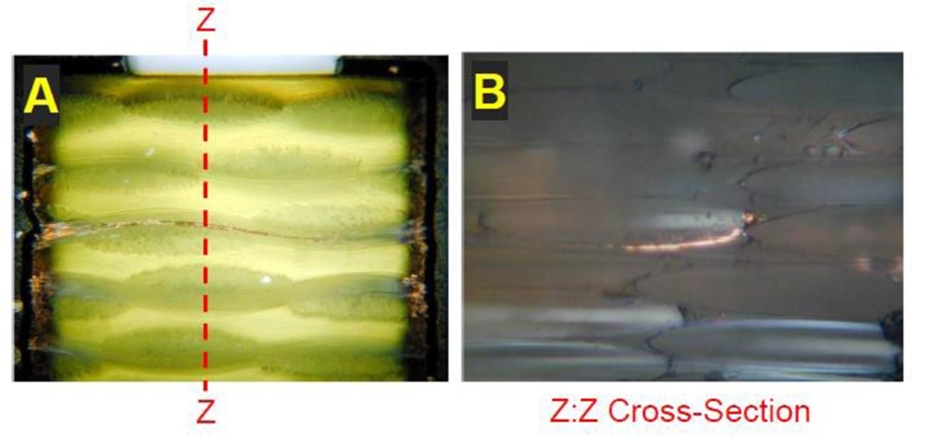
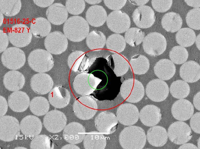
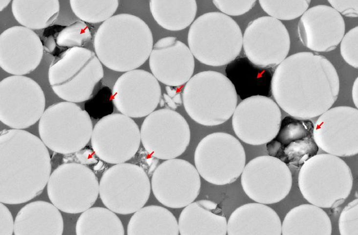
What does CAF look like?
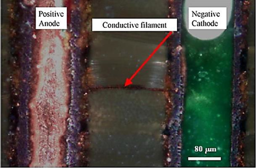
What exactly is Electro-migration (EM) for CAF?
- Electro-migration of e– and Ions under the influence of applied voltage (PCB Internally)
- Electro-migration of e– and Ions Between Vias (HW-HW)
- In 2 different electrical nets
- At different potentials (one hole relative to the other)
- Must be an electrical pathway between hole pairs
- not the pure resin
- but at the glass/resin interface or Hollow-Fiber (microscopic)
- resin holes between the glass filaments (macroscopic)
Elements Needed for CAF / EM Failure
Pathway
- Separation of Glass Fiber / Epoxy Interface
Material Fabrication – Incomplete wetting glass/resin PCB + PCBA Fabrication – Thermal / Mech / Chem Stresses Degradation of Glass/Resin Bond (Temp / Humidity)
- Hollow Glass Fiber
Moisture
PCB + PCBA Fabrication
Final Part Field Operation
Applied Bias Voltage
Operation of the Final Part (between Different Nets at Different Potentials)
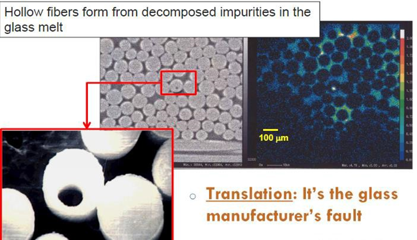
Hollow Fiber Path Formation Example 1
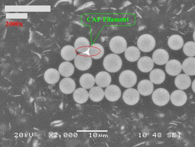
Hollow Fiber Path Formation Example 2
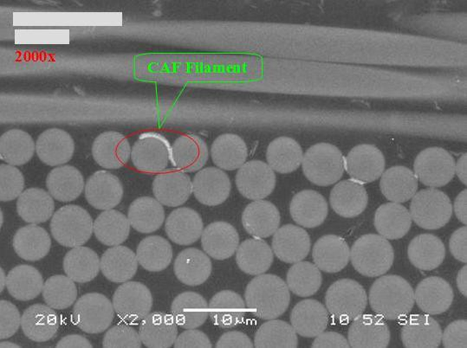
Hollow Fiber Path Formation Example 3
Glass Cloth / Resin Perspective

Topographical View of Typical Glass Fabric

Vertical X-sect of Typical-Glass Fabric in MLB
4 Potential modes of CAF / EM failure (3 can be prevented by the use of correct Buttercoats)


Importance of Buttercoats
Drill Hole wall to Drill Hole wall with CAF filament growth.


DHW to Feature (Trace/Clearance) – Undesirable

DHW to Feature (Trace/Clearance) – desirable

Insufficient Resin Buttercoat

Acceptable Buttercoat
Factors influencing Electro-migration (EM) and subsequent CAF growth.
Design
- Proximity of Holes / Features – Critical
Materials
- Heavier Glass (7628) structures perform worse for EM / CAF
- Lighter Glass (106) structures can perform worse for EM / CAF
- Glass fiber distribution can cause filament nesting.
Type of Glass, Treatment, and Resin marriage
- Environment (End application)
Higher voltage/humidity/temperature -Accelerates.
- PCB Processes May Need to optimize for best CAF performance (Lamination / Drill / De-smear)
Low – Medium Layer Count Challenges to CAF Success
- Heavy Glass (7000 series): DSR – 4L, 6L, 8L, 10L
- Heavier Glass structures perform worst for CAF.
- Lower Resin Content vs Lower CTEz-axis Materials
- Low CTEz-axis – Ability to pass ATC Thermal Cycling
- Low Resin Content Not good for CAF – Not enough butter coat
- Compressed Stack-ups
- Glass touching copper – Stress Points + Shorter CAF Pathway
- Low Cost / Low Layer Count Solutions
- 7628 stack-ups – not good for CAF
- Dicy Materials preferred for cost – not good for CAF or LF
- Design Features shrinking – not good for Best CAF Perf
Best CAF Resistant Materials
- Proper Marriage of Glass / Glass Surface Finish to Resin Enhanced CAF Process @ Material Supplier
- Learn by CAF Testing TVs – Generally, 12,30 mil DHW to DHW testing coupons.
- Two Important Elements Needed for Best Resistance are the Best Glass match to Resin System and the Enhanced CAF Process at the Material Supplier
Best Glass Choices
- Not always obvious & Need to Test to find out.
- Some Best Choices can be more expensive such as Japanese Glasses
- Sometimes there are cost-effective solutions that depend on DHW to DHW spacings, Applied Voltages, and Environment.
CAF Enhanced Process at Material Supplier
- Better Surface Wetting or Glass Wet-out.
- Lower Viscosity Resin adjustment
- Glass Cloth prewetting
- Slower Treater Speed
Material Influencing Factors for Electro-migration (EM) and Subsequent CAF Growth.
- Right Glass/Finish
- Passing spacings can go from 17 mils to >30 mils.
- Enhanced CAF Process at the Material Supplier
- Passing spacings can worsen by 10 mils DHW to DHW
- Improper wetting of glass filaments – easy pathways
- Tripple Point voids – easy pathways
- All can lead to EM/CAF
CAF Materials -Pathways
Example of Non-wetted Glass in Hi-Tg Filled Phenolic of a 1501 core in Warp direction Material Supplier changing Treater Process and Spread Glass to both Warp + Fill.

Example of Non-wetted Core Glass or Classic Tripple Point in Mid-Tg Filled Phenolic Material Supplier Forgot to run Enhanced CAF Process at their Factory.


Best CAF Resistant Material Choices (~0-20%) of Total Material Cost
- Pre-selected Glass Type / Glass surface finish
- CAF Enhanced Process at Material Supplier
Some Material Suppliers include Enhanced CAF Processes automatically as part of their Standard Process and cost structure and some do not.
Special Glass is a Major Cost Adder of the above Two and not the Enhanced Process.
Other Perspectives
DHW-DHW
- 25 mil – Most good CAF Resistant Materials Should Pass (Glass/Resin?)
- 20 mil -Some Risk for good or best CAF Resistant Materials
- 15 mil – High Risk for best CAF Resistant Materials
- 12 mil – Best CAF Resistant Materials will most likely Fail.
Material Suppliers
- Better Understanding of variables needed: Glass, Process, Constructions, Better Marriages of Glass/Resin
Potential Applications Susceptible to Electro-migration Failure (Hard Leaks)
Automotive Industry
- Brake Controllers
- Other Controllers
Telecommunications Industry
- Any circuit with a high impedance – is radically affected.
- Phase Locked Loops (control of the system clocks)
- Analog and RF circuits
Other Industries
- A-D and D-A converters
EMSxchange Enables you to select a Printed Circuit Board, PCB Assembly, cable & wire harness assembly, and box-build suppliers meeting your Required Electronic Manufacturing Capability, capacity, and Certification Criteria from a global Electronic contact manufacturer base.
EMSxchange takes complete responsibility and ownership for your electronic manufacturing process and all its deliverables from contract manufacturing supplier selection to manufacturing to quality inspection to shipment and delivery to your door.
EMSxchange Electronic Manufacturing Partners Profile includes:
Argus Systems (AESPL) – PCB, PCBA, Cable Assembly, Box Build, Testing.