
PCB Assembly Solder Quality Analysis
There are tell-tale signs that indicate a good solder joint when soldering components on a circuit board. A good solder joint, for example, will have solder applied to both elements being linked and will have no air pockets. The significance of good solder connections in PCB quality control is well understood, as poor junctions can result in unreliable signal transfer, tombstoning, and no signal flow at all.
It is true that your Contract Manufacturer is responsible for the solder joints on your board. It all comes down to your Contract Manufacturer’s assembly procedure and dedication to quality. The quantity and types of tests performed during the assembly of your board are a solid indicator of this committment.
Scope of this blog is to describe high level process for PCB Assembly Solder Quality Analysis verification
Tools & Equipment
- 2 & ½ D digital stereoscope
- Microscope
- Digital Xray Machine
- IC extractor & IC Pull-out hooks & wire assembly
- Pull out strength meter with weight
Standard followed
- IPC-A-610
- Assembly Class specified as per product Requirement
- Class1
- Class2
- Class3
Steps Performed
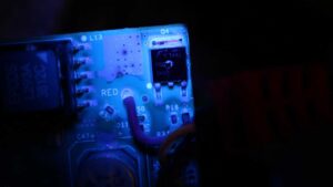
- Solder Joint analysis with visual inspection
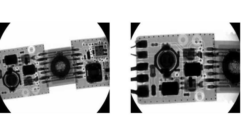
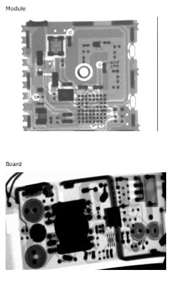
- IC/Devices soldering quality analysis with x ray for specific parts
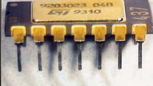
- Pull out strength measurement for parts for specific parts
- Parameters
Test Report
Acceptable Solder Criteria
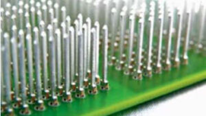
Acceptable Solder Criteria for Through Hole Components
- Circular wetting of solder of the lead and plated hole barrel on the component side.
- Plated hole fill.
- Circular fillet and wetting of solder of the lead and plated hole barrel on the solder side.
- Percent of the land area covered with solder on component side.
- Percent of the land area covered with solder on the solder.
Acceptable Solder Criteria for Chip Components
- Maximum Component Side Overhang
- Maximum Component End Overhang
- Minimum End Joint Width
- Minimum Side Joint Length
- Maximum Fillet Height
- Minimum Fillet Height
- Minimum Solder Thickness
- Minimum End Overlap
Acceptable Solder Criteria for J Lead Components
- Maximum Lead Side Overhang
- Maximum Lead Toe Overhang
- Minimum Lead End Joint Width
- Minimum Side Joint Length
- Maximum Fillet Height
- Minimum Heel Fillet Height
- Minimum Solder Thickness
Acceptable Solder Criteria for Gull Wing Components
- Maximum Lead Side Overhang
- Maximum Toe End Overhang
- Minimum End Joint Width
- Minimum Side Joint Length
- Maximum Heel Fillet Height
- Minimum Heel Fillet Height
- Minimum Heel Fillet Thickness
Example X-ray reference

EMSxchange Enables you to select a Printed Circuit Board assembly suppliers meeting your Required PCBA Manufacturing Capability, capacity and Certification Criteria from a global PCB Assembly manufacturer base. EMSXchange takes complete responsibility and ownership for your electronic manufacturing process and all its deliverables from contract manufacturing supplier selection to manufacturing to quality inspection to shipment and delivery to your door. EMSxchange Electronic Manufacturing Partners Profile includes:
Argus Sytems (AESPL) – PCBA, Cable Assembly, Box Build.
Cerra Systems inc – PCB Manufacturing.