What is FMEA?
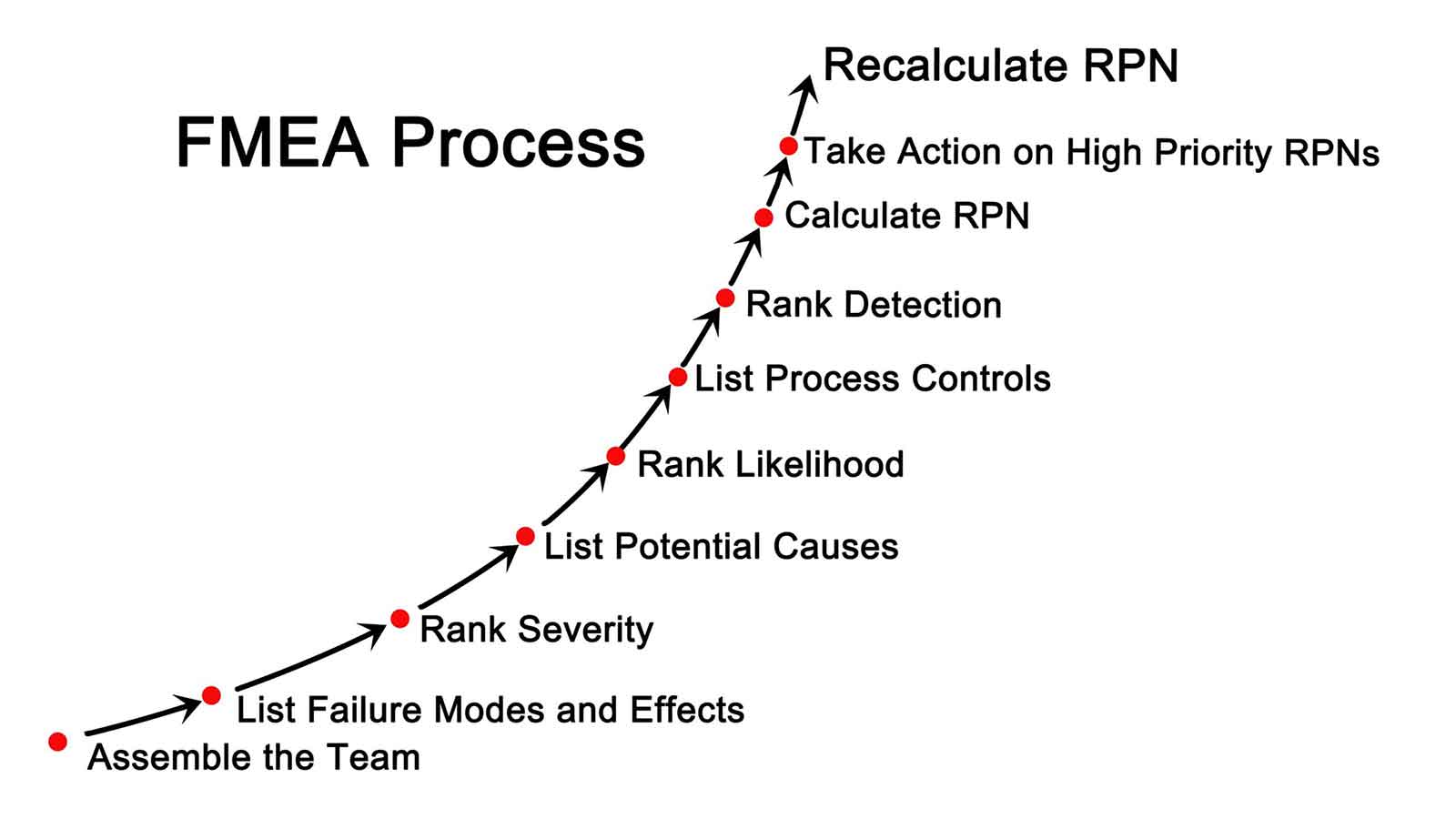
FMEA (Failure Mode and Effects Analysis) is a method for identifying probable failure modes in a system, as well as their causes and effects, by analysing as many components, assemblies, and subsystems as possible. Failure modes and their impacts on the rest of the system are recorded in a separate FMEA spreadsheet for each component. There are many different kinds of worksheets like this. When mathematical failure rate models are integrated with a statistical failure mode ratio database, an FMEA can be turned into a quantitative study. It was one of the earliest highly structured and systematic failure analysis methodologies. It was created in the late 1950s by reliability engineers to investigate problems that could come from military system failures. An FMEA is usually the first step of a system reliability study.
FMEA is a method for determining where certain systems or machinery may fail. The most obvious advantage of this examination is that it allows a corporation to be proactive. It’s a great tool to be able to analyse your components and subsystems while also detecting probable system failure modes.
The systematic technique of FMEA enables you to predict possible failures in the design or manufacturing phases of a product. FMEA can be divided into two categories: Design FMEA (DFMEA) and Process FMEA (PFMEA).
There are three categories in DFMEA and PFMEA. To assess the amount of threat, these categories have a scoring matrix that spans from 1 to 10. The following are the details:
- Severity: This category indicates the level of risk to the end consumer, with 1 indicating a low risk and 10 indicating a significant danger to the final customer.
- Occurrence: The chance of the risk event occurring is shown below; a 1 indicates a low likelihood of the risk occurring, while a 10 indicates a very high likelihood of the risk occurring.
- Detection: Finally, we determine whether or not a failure is likely to be detected. This is inversely proportional, as opposed to the previous scores. A 1 suggests that the process is likely to notice a failure, whereas a 10 indicates that the process is unlikely to detect a failure.
Adding the three scores together (Severity * Occurrence * Detection) after rating each category’s risk. A Risk Priority Number is the result of this calculation (RPN). The RPNs are then sorted in ascending order, and you can take action on the highest risks to reduce the overall risk.
Failures, in a nutshell, are faults or defects that can be possible or actual. Failure modes, on the other hand, are the ways in which a device or process fails. In terms of failure impacts, this refers to the various ways in which these failures can result in flaws, waste, or adverse outcomes. Device or process failures, bodily damage, or a decline in product quality are all examples of this. Other systems may be harmed as a result of these system failures. Effects analysis, as you can see, is a study of how failures affect various system components.
What is FME for PCBA Development?
A well-known well-structured procedure-based way of analysing a design or process is failure mode and effects analysis. The goal of design FMEA or DFMEA, which originated in the aerospace industry as a technique of preventing failures for which root cause analysis (RCA) proved ineffective, is to identify risks and devise actions that may be taken to reduce the likelihood of failures for the system being designed. This strategy is usually used on new designs or existing designs that are being modified (s).
Process failure mode and effects analysis (PFMEA, on the other hand, is an algorithm that aims to eliminate failure occurrences that could stop a process or lower the quality of the output. Any such occurrence is a risk, and PFMEA is used to detect, classify, and manage those risks.
Failure Mode & Effects Analysis (FMEA) for PCB Assembly Process
Solder Paste Screen Printing
Process Function: Solder Paste Screen Printing
Potential Failure Mode: Smudged Paste
Potential Effect(s) of Failure: Solder Shorts, Misplacement, Solder balls/splashes, Excess or Insufficient solder on pad
Potential Cause(s) of Failure: Improper Handling, Damaged / Non-planar stencil, Tooling blocks not located, Correctly/precisely, Printer not maintained properly/regularly, Auto cleaning not functioning.
Process Function: Solder Paste Screen Printing
Potential Failure Mode: Wrong Paste Used
Potential Effect(s) of Failure: Contamination, Dry solder, mixed chemistry, Non- wetting
Potential Cause(s) of Failure: Wrong paste requested, Wrong paste issued, Wrong jar used/ Wrongly labelled.
Process Function: Solder Paste Screen Printing
Potential Failure Mode: Missing solder Paste
Potential Effect(s) of Failure: Opens, Missing and misplaced components.
Potential Cause(s) of Failure: Blocked apertures in stencil, Damaged stencil, Wrong stencil used, Paste adhering to squeegee blades, Small Squeegee blades.
Process Function: Solder Paste Screen Printing
Potential Failure Mode: Non-uniform Printing
Potential Effect(s) of Failure: Shorts, Opens, Solder Balls Missing, misplaced comp.
Potential Cause(s) of Failure: Printer wrongly set-up, PCB’s, Stretched stencil, Wrong block support, PCB not loaded properly into printer.
Process Function: Solder Paste Screen Printing
Potential Failure Mode: Contamination
Potential Effect(s) of Failure: Solder balls, Opens, Poor Solder quality, Scrap.
Potential Cause(s) of Failure: Incorrect handling of PCB, Wrong paste used, Dirty block support, Wrong cleaning fluid in printer, Wiped cards, not cleaned properly, Paste expired, Process machines not clean, Auto cleaning not functioning.
Process Function: Solder Paste Screen Printing
Potential Failure Mode: Paste Bridging
Potential Effect(s) of Failure: Solder Shorts, Solder balls.
Potential Cause(s) of Failure: Damaged stencil, Wet screen, Wrong stencil thickness, Insufficient Squeegee Pressure.
SMT Pick & Placement
Process Function: SMT Pick & Placement
Potential Failure Mode: Missing components/ Component Spillage.
Potential Effect(s) of Failure: Rework, test fails and scrap.
Potential Cause(s) of Failure: Faulty feeders, Wrong feeder / pitch, Incorrect program / teaching, Incorrectly shaped part / Part Data, Damaged, wrong nozzle, Board not clamped in machine, Wrongly set-up board supports, Dry paste on boards, Machine interrupted during cycle, Faulty spool valves (cp only).
Process Function: SMT Pick & Placement
Potential Failure Mode: Incorrect part.
Potential Effect(s) of Failure: Rework, test fails and scrap.
Potential Cause(s) of Failure: Wrong part placed on machine, Program Error, Reel labelled incorrectly by supplier, Reel labelled incorrectly by stores, Wrong program / rev.
Process Function: SMT Pick & Placement
Potential Failure Mode: Reversed mounted part.
Potential Effect(s) of Failure: Test fails / rework.
Potential Cause(s) of Failure: Wrongly packaged from supplier, Tray placed incorrectly in I.P.3, Program Error, Incorrect Assembly Height.
Re-flow soldering
Process Function: Re-flow soldering
Potential Failure Mode: Warped cards.
Potential Effect(s) of Failure: Scrap.
Potential Cause(s) of Failure: Incorrect profile setting, Incorrect track width, Incorrect centre support rail setting.
Process Function: Re-flow soldering
Potential Failure Mode: Misplaced parts.
Potential Effect(s) of Failure: Rework, test fails and scrap.
Potential Cause(s) of Failure: Incorrect profile setting, Faulty profile card, Faulty heater, Transport error.
Process Function: Re-flow soldering
Potential Failure Mode: Paste not wetting properly.
Potential Effect(s) of Failure: Rework, test fails and scrap.
Potential Cause(s) of Failure: Incorrect profile setting, Faulty profile card, Faulty heater, Faulty fan.
Visual Inspection Of PCB Assemblies Inspect to IPC Class 3.
Process Function: Visual Inspection Of PCB Assemblies Inspect to IPC Class 3.
Potential Failure Mode: Reject good cards.
Potential Effect(s) of Failure: Unnecessary repairs, potential damage.
Potential Cause(s) of Failure: Inadequate training to standards.
Process Function: Visual Inspection Of PCB Assemblies Inspect to IPC Class 3.
Potential Failure Mode: Accept bad cards.
Potential Effect(s) of Failure: Customer returns, Incomplete verification of product.
Potential Cause(s) of Failure: Inadequate training to standards.
EMSxchange Enables you to select a Printed Circuit Board assembly, cable & wire harness assembly and box build suppliers meeting your Required PCBA Manufacturing Capability, capacity and Certification Criteria from a global PCB Assembly manufacturer base. EMSXchange takes complete responsibility and ownership for your electronic manufacturing process and all its deliverables from contract manufacturing supplier selection to manufacturing to quality inspection to shipment and delivery to your door. EMSxchange Electronic Manufacturing Partners Profile includes:
Argus Sytems (AESPL) – PCBA, Cable Assembly, Box Build.
Cerra Systems inc – PCB Manufacturing.


