
Using Metal Core Printed Circuit Board (MCPCB) as a Solution for Thermal Management
The designs of electronic devices and systems are being continuously improved by becoming smaller in size and faster in communication speed. The potential risk associated with these specific design improvements will be an increase in power density and, consequently, a greater risk of thermal problems and failures.
At the same time, the prevailing use of circuit boards integrated with power devices such as motor controllers and drivers, light emitting diode (LED) lighting modules, power supplies and amplifiers, and regulators for TV, etc., drive to the use of a proper thermal management system while designing these kinds of printed circuit board (PCB).
Importance of thermal management
Thermal management of an electronic system encompasses all of the thermal processes and technologies that must be employed to remove and transfer heat from individual components to the system’s thermal sink in a controlled manner. The objective of thermal management is to ensure that the temperature of all components is maintained within functional and absolute maximum limits.
The functional temperature limit is the range within which the electrical circuits can be expected to meet their specified performance or cause logic errors. The absolute maximum temperature limit is the temperature that a portion of the component may be safely exposed. Temperatures exceeding the limits can cause physical destruction or may result in earlier failure of electronic components in the system.
The failure rate F of an electronic component is directly proportional to heat and can be described by the Arrhenius equation:
F = Ae(-Ea/kT)
where A = constant
F = failure rate
EA = activation energy in electron volts (eV)
K = Boltzmann’s constant (8.63 x 10⁻⁵ eV/K)
T = junction temperature in Kelvin
If a device with activation energy EA = 0.65eV were operating at 50 Degrees C and its temperature raised to 60 Degrees C, the failure rate would increase by a factor of 2.
Hence, efficient thermal management is crucial to:
- increase the shelf-life of systems
- reduce failure rates
- increase thermal durability
- enable the design of high-circuit density
- enable the use of higher power density
Thermal conductivity is a material property that describes the ability of a material to conduct heat after the heat has entered the material. As shown in Table 1, conventional PCB materials such as FR4 and PI share the lowest thermal conductivity and are not capable of meeting the continuously increasing demand of the thermal requirement of the high power dissipation PCB. One of the current approaches to address this thermal dissipation problem is the use of a Metal Core Printed Circuit Board (MCPCB).
Different types of MCPCB
A MCPCB consists of a number of layers including a dielectric sandwiched between two metal layers. One of the metal layers, typically a 1Oz to 10Oz copper foil, acts as a circuit layer for electrical connections, while the other serves as a heat spreader. Most of them are made of aluminum or copper alloy (Table 2), but iron alloy or even carbon is also available on the market.
Choosing the type of materials as a heat spreader lies on the applications of the MCPCB. For instance, aluminum should be used if a lighter weight of MCPCB with gentle heat dissipation is required. By contrast, copper offers higher heat conductivity, in other words, a higher heat dissipation rate, but it is heavy in weight.
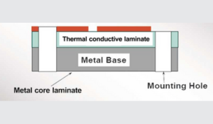
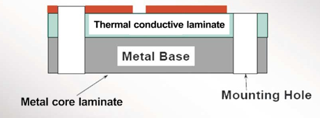
There are various construction designs of the MCPCB available (Figure 1a, 1b, 1c, 1d, 1e, 1f). The most common types of MCPCB are single-layer and two-layer MCPCB. The former is simply fabricated by print and etch on the thermal core laminate. The latter requires an additional pressing step to laminate the imaged thermal conductive laminate and metal base (also known as metalcore) together. This is similar to the processing steps of producing multilayer and hybrid MCPCB.
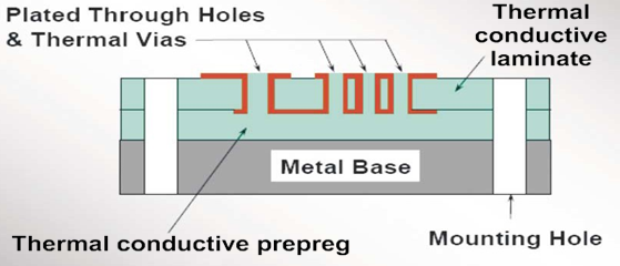
The processing steps of the MCPCB with the metal base embedded in the PCB are comparatively complex as hole plugging is required after primary drilling on the metal base in order to isolate it from the circuitry.
| Materials | Thermal conductivity (W/m-K) |
| FR4 | ~ 0.3 |
| Polyimide | ~ 0.3 |
| PTFE Ceramic | 0.5 – 0.66 |
| Thermally conductive dielectric | 1.0 – 4.0 |
| Alumina | 33 |
| Beryllium oxide | 251 |
| Aluminium 5052 | 150 |
| Aluminum 5052 | 385 – 400 |
Table 1: Thermal conductivity of some common electronic materials
| Metal base plates | Material |
| Aluminium | 1050, 5052, 6061 |
| Copper | C1100 |
Table 2: Common alloy used as metal base plates
1a) Single-layer MCPCB
1b) Two-layer MCPCB
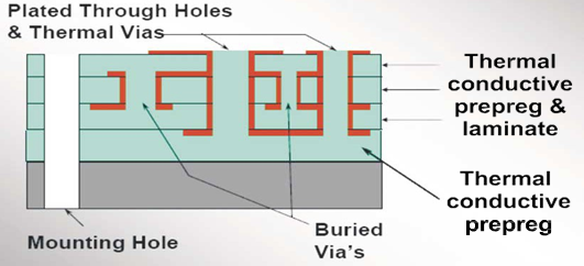
1c) Multilayer MCPCB
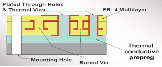
1d) Hybrid MCPCB
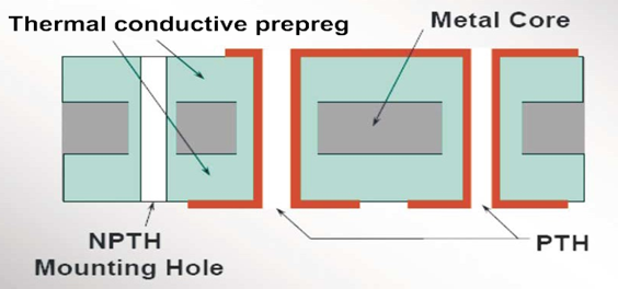
1e) Metal core inside PCB
Thermal conductive dielectric used in MCPCB
The most commonly used dielectric in the thermal conductive laminate is a special filler-matrix composite as shown in Figure 2 (right). It offers a low thermal resistance path for heat conduction, acts as a bonding media, and is an insulation layer between the circuitry and the heat spreader.
In general, the thermal conductivity of this special insulation dielectric is 4 – 16 times higher than conventional FR4 dielectric, thereby expediting heat conduction. A typical single-layer metal core laminate is shown in Figure 2.
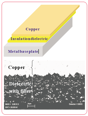
Figure 2: (top) A schematic drawing of a single-layer metal core laminate, (bottom) A SEM image showing the layer configuration of metal core laminate
Compared with ceramic substrates such as alumina, aluminum nitride, and beryllium oxide, which are also being used as heat dissipation media, MCPCB offers lower costs and better mechanical strength. Even though the thermal conductivity of the dielectric of MCPCB is lower than that of ceramic substrates, the feasibility of making a thinner dielectric may shorten the thermal conduction path between its adjacent layers and therefore be capable of accommodating this drawback to a certain extent.
Modelling of the thermal conductivity of the dielectric
The effective thermal conductivity of the dielectric of the thermal conductive laminate depends on many factors as illustrated in Figure 3. Choosing the right combination is the key to producing a high-performance MCPCB.
Among them, the types and percentages of fillers are of paramount importance. Some models have been established to predict the possible outcome of the thermal conductivity of different formulas. One of these examples, the Nielsen model (Lewis TB, et al), as shown below, is applicable to low and medium filler loading composites (<20 vol. %).
This model considers the effect of the shape, orientation, and packing factor of fillers on the thermal conductivity. Equation (1) gives the mathematical relationship of the model. However, it doesn’t consider the effect of the formation of conductive chains of fillers at high filler loading.
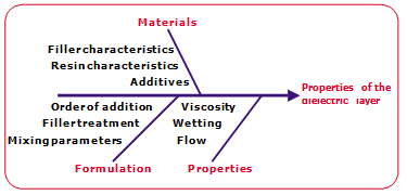
Figure 3: A “Fishbone” diagram showing the key factors that affect the properties of the dielectric layer of MCPCB

Where
Ke effective thermal conductivity of composite materials
Kf thermal conductivity of fillers
Km thermal conductivity of the matrix
Vf volume fraction of fillers
Vm maximum packing fraction of the filler phase
As dimensionless shape factor depends on the geometry of fillers and is related to the generalized Einstein coefficient.
Another example, the Agari-Uno model, which has taken into account the effect of the formation of conductive chains of fillers at high filler loading is illustrated as follows:
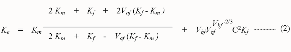
where Vaf is the volume content of fillers not contributing to forming conductive chains
Vbf is the percentage of fillers contributing to forming conductive chains
C2 is the geometrical factor that connects the observable conductivity with the random assembly of conductive chains.
This model is useful to predict the thermal conductivity of a high filler contents dielectric but experimental trials are required to find out the constant in the model in advance
Both of these models help the PCB industry to find out the suitable formula to produce the insulation dielectric of the MCPCB with desired thermal conductivity value.
Characteristics of the MCPCB laminate
Other than the high thermal conductivity, the dielectric layer of MCPCB also requires high insulation resistance, high glass transition temperature (Tg) and decomposition temperature, high adhesion strength with a copper and base metal plate, proper dielectric constant, and manufacturability.
The first three characteristics are inter-correlated; a high Tg and decomposition temperature of the dielectric layer enables the board to continuously serve in a high-temperature condition without causing any harm to its other properties such as insulation resistance or resulting in any defects such as delamination.
Same to thermal conductivity, the characteristic of dielectric constant also depends on the type and the percentage of fillers added to the resin matrix. Table 3 shows the dielectric constant of some common ceramics that can be used as fillers to enhance thermal conductivity.
The use of a higher dielectric constant of ceramics will result in a higher dielectric constant of the insulation dielectric of the MCPCB, and the amount it added will further intensify this effect. Selection of the types of fillers depends on the applications of the MCPCB, alumina may be more appropriate if low-cost products with less thermal conductivity are required, while boron nitride is more suitable for high-speed applications due to its lower dielectric constant.
The last one, manufacturability, affects the production yield of metal core laminates and the MCPCB in laminate manufacturers and P CB fabricators respectively. The effect of the percentage of filler contents on the performance of MCPCB is twofold. Firstly, it has a direct influence on the rheology of the resin matrix which may affect resin flow during the lamination of the metal core laminate or MCPCB. Insufficient resin flow may result in resin void or poor adhesion strength between the dielectric and the metal base plate or copper foil. Secondly, in combination with the effect of the hardness of the filler, it affects the machinability of the MCPCB, too hard a filler leads to worn out of drill bits and may result in poor hole quality.
| Ceramic | Dielectric constant, Dk | Thermal conductivity,y | KNOOP Hardness,s |
| Boron nitride | 4.2 | 55 | 205 |
| Alumina | 9.7 | 33 | 2000 |
| Beryllium | 6.7 | 251 | 1200 |
| Aluminum | 10 | 117 | 1200 |
Table 3: Characteristics of ceramics that are used as filler for MCPCB
Summary
With the increasing demand for PCBs that are of high power and high circuit density, thermal management has become crucial while designing PCB in order to ensure their reliability. MCPCB is now the most widely used product to address this problem.
It is proven to be able to enhance the thermal reliability of the system. It expedites heat dissipation from its generators such as LED through a thermal conductive dielectric to a heat spreader so that its service life is extended.
Several types of MCPCB are available on the market but the single-layer one is still prevalent due to its simplicity. Mastering this MCPCB technology requires not only the technique to fabricate it in PCB shops but also the know-how of how to fabricate the thermally conductive dielectric in substrate shops. Currently, filler-matrix composite is used as MCPCB laminate and its properties and manufacturability depend on the type of fillers, coupling agents, and resins used.
With the help of the Nielsen model and the Agari-Uno model, laminate manufacturers can formulate this dielectric as well as the metal core laminate according to the cost and application requirements of the products. However, the MCPCB manufacturing technology and most of the patents are mainly held by foreign substrate suppliers and the technology level of the local PCB industry is lagging behind. Extensive effort and research studies in the local industry are needed in order to shorten this technology gap and produce MCPCB at a lower price.
Thermal dissipation capable of sustaining high temperatures will play a major role in future power products and power circuit board designs”
EMSxchange Enables you to select a Printed Circuit Board, PCB Assembly, cable & wire harness assembly, and box-build suppliers meeting your Required Electronic Manufacturing Capability, capacity, and Certification Criteria from a global Electronic contact manufacturer base.
EMSxchange takes complete responsibility and ownership for your electronic manufacturing process and all its deliverables from contract manufacturing supplier selection to manufacturing to quality inspection to shipment and delivery to your door.
EMSxchange Electronic Manufacturing Partners Profile includes:
Argus Systems (AESPL) – PCB, PCBA, Cable Assembly, Box Build, Testing.