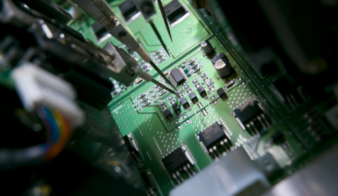
Manufacturing defect analyzer (MDA)
The Manufacturing Defect Analyzer is a tool for detection of manufacturing defects within a printed circuit board (PCB). MDA Testing is a method usually applied for large-scale production orders, and functions as a pared down version of In-Circuit Testing (ICT). Manufacturing Defect analysis is Typically performed after Automated Optical Inspection (AOI) and final Visual Inspection is complete.
As the majority of manufacturing defects are connectivity issues, The MDA focus is to make measurements of continuity. This method employs a “Bed of Nails” fixture that is able to quickly test connectivity of the finished PCB against a client’s Netlist file. This significantly reduces its cost making it more viable in many areas of test.
MDA Testing is not Standard PCB Options for Prototype PCB Assembly or Low-Volume PCB Assembly. Customers who require MDA should be aware That They will incur additional cost and lead time for their project.
Each PCB project is unique, so part of the time and cost requirement for MDA Testing is the design and development of a custom fixture for the project. Once a fixture is built, the testing process itself is quite rapid.
MDA BASICS
MDA is based around the concept that the design of a board has been previously proven, and parts are reliable and very few defective components will be delivered. Hence, it should only be manufacturing defects that will impact the performance of a board or assembly. As most of the defects consists of solder splashes and poor or open joints, then the majority of failures will be detected by testing for a relatively simple spectrum of failure types.
While Manufacturing Defect Analyzers are primarily focused on the detection of the very basic faults, even the most basic testers these days will also detect missing components. Often the tester will be able to detect the presence of resistors, capacitors and transistors. The detection of integrated circuits can also be achieved using the protection diodes to indicate whether the component is correctly placed.
The tester makes connection to the board under test using a bed of nails fixture, and this means that a different fixture is generally required for each board. It needs to contact specific points on the board, where often there may be a test point or land area for the probe.
Like other forms of In-Circuit Tester, an MDA will use the printed circuit board CAD data for the generation of the fixture design and the test program. This often allows up to around 80% of the test program to be generated automatically.
MDA Advantages / Disadvantages
Manufacturing defect analyzer advantages and disadvantages need to be carefully considered when choosing which type of tester and test technology to be used.
The main difference between MDA Testing and ICT is that MDA Testing only tests for connectivity on the board Similar to PCB Electrical Testing, while ICT checks specific voltage and current levels throughout the PCB.
When you submit your request for MDA Testing, engineering teams will carefully review PCB Design Flies and develop a targeted testing workflow, and begin working on the design for your custom test fixture.
ADVANTAGES
- Machine is much less costly than a full ICT.
- Can detect open and short circuits which form the major number of defects. Which can detect some values dependent upon the MDA capability.
- An MDA machine is very much simpler than a full ICT. This makes it an attractive proposition for many situations, particularly within smaller companies.
- The capital expenditure investment of a full ICT machine may not be viable. An MDA machine is very much simpler than a full ICT.
- This makes it an attractive proposition for many situations, particularly within smaller companies.
- In many other situations a Manufacturing Defect Analyzer may be a viable option is where the fault spectrum does not warrant a full In-Circuit test. This decision can only be made in the light of an analysis of existing fault spectra for a given manufacturing line.
DISADVANTAGES
- Limited component diagnostics.
- Still requires bed of nails fixture and its associated costs.
- Component access can be an issue with current board density levels
EMSxchange Enables you to select a Printed Circuit Board assembly, cable & wire harness assembly and box build suppliers meeting your Required PCBA Manufacturing Capability, capacity and Certification Criteria from a global PCB Assembly manufacturer base. EMSXchange takes complete responsibility and ownership for your electronic manufacturing process and all its deliverables from contract manufacturing supplier selection to manufacturing to quality inspection to shipment and delivery to your door. EMSxchange Electronic Manufacturing Partners Profile includes:
Argus Sytems (AESPL) – PCBA, Cable Assembly, Box Build.
Cerra Systems inc – PCB Manufacturing.


